
Detecting a higher voltage on a Raspberry PI pin
In a Raspberry PI application I made recently I wanted to detect if a 24 volts circuit was powered. As you probably know the Raspberry PI pins can only handle 3.3V input. I solved this with a simple optocoupler circuit with help from Nils and the internet.
Note: this circuit turned out to be a little buggy in my application, it goes from high to low over time, I managed to solve it with programming, but keep this is mind.
An optocoupler or opto isolator is a component that lets you control one circuit with another circuit, a bit like a transistor, but the two circuits are totally separated from each other. Internally the optocoupler uses light to interact between the circuits.
Here’s the circuit:
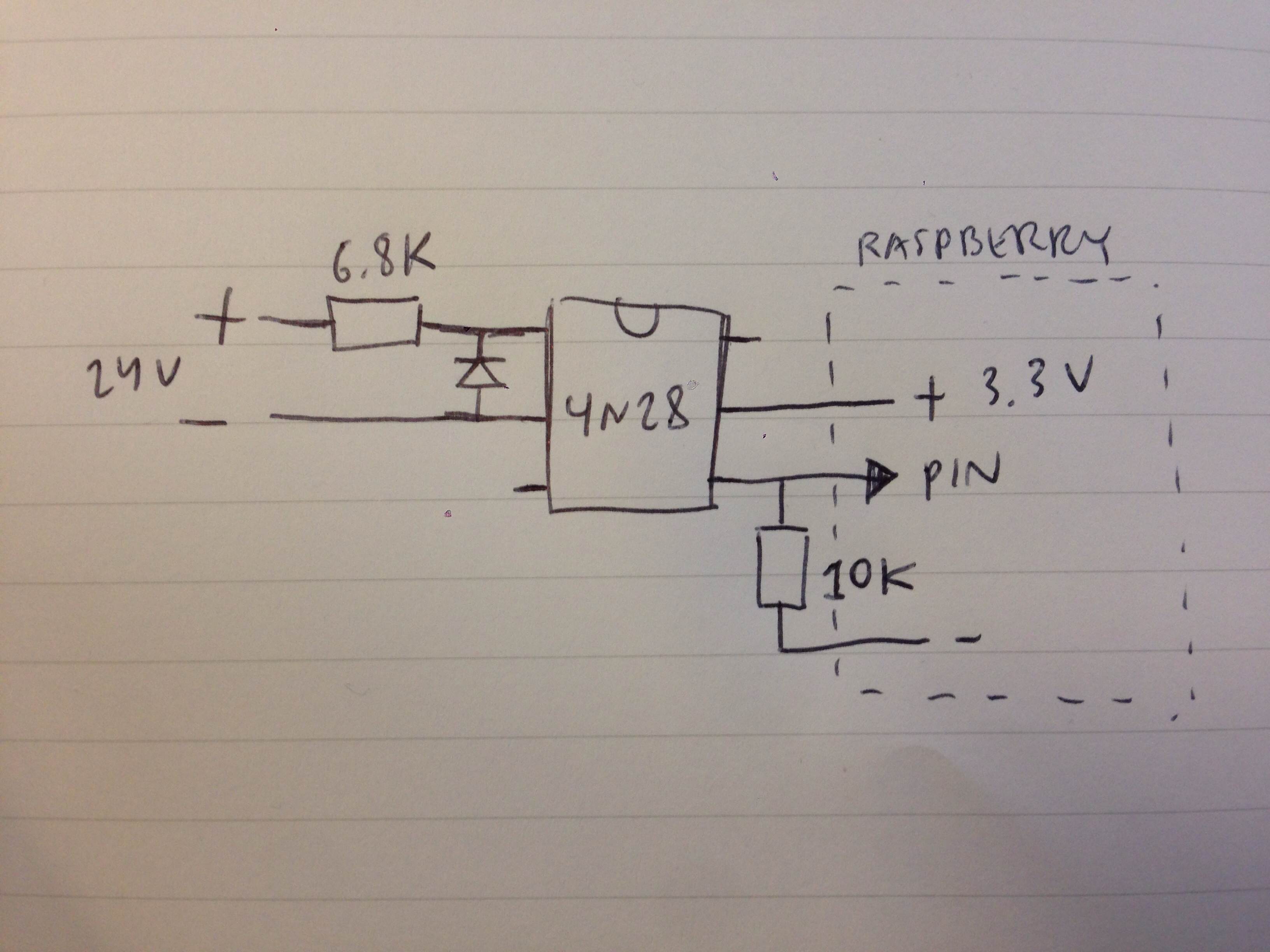
On the left hand side of the 4n28 optocoupler is the 24V circuit. The resistor is there to limit current I think. I think the diode can be left out but Nils said it’s there for bad stuff that can happen under some circumstances. Whenever the left hand circuit is active it will activate the one on the right hand side.
On the right hand side is the Raspberry. 3.3v is connected to the input of the circuit, and then the output is connected to a pin. When the circuit is active the pin will read high, when not it will read low via the resistor to ground/minus.